Why are ASME B16.5 Standards important?
Engineers rely on ASME/ANSI standards and codes to define pressure-temperature ratings, materials, dimensions, tolerances, marking, testing, and methods of designating openings for pipe flanges and flanged fittings. The engineering of piping systems help make sure that they meet the prescribed requirements for pressure integrity and safety.
The standards and codes help to determine the characteristics of pressure integrity and simplify the design rules.
The difference between the codes and standards is helpful for the designers with detailed flange specifications and designs for the components. Here are the frequently encountered rules and standards:
1. Minimum wall flange thickness
2. Permissible materials for construction
3. Allowable work stresses
Structural behavior is due to the effects of thermal expansion, live loads, seismic loads, deadweight, internal pressure, and other imposed external or internal loads.
However, the piping codes provide no design rules for standard in-line components like standard valves and flange fitting components. The designing of these classes of elements happens through the reference to the industry standards.
1. Pressure-integrity standards: The standards help in providing uniform minimum-performance criteria. The designing and manufacturing of the components to the same standards will be helpful to function equivalently.
It helps to remember that pressure integrity is not entirely synonymous with leakage integrity.
During the operation and test, pressure integrity is one assurance when it comes to the leak-tight condition and does not account for the entire risk profile to the structural stability of the pressure boundary or added stresses.
2. Dimensional standards: The standards define the configurations and parameters for piping components, ensuring parts from different manufacturers are physically interchangeable. This consistency is essential for maintaining compatibility across systems.
However, meeting ASME flange dimensional standards doesn’t guarantee identical performance among similar products. Various ASME standards also include pressure-temperature ratings, which help determine the suitability of components for specific applications.
As per the ASME B16.5, 2017, there are:
a. 16 nonferrous metal groups
b. 10 high-alloy steel material groups
c. 8 Low-alloy steel and carbon material group
If you want to check the complete lists and tables, you can check them on ASME B16.5, 2017. (Standard: “Pipe Flanges and Flanged Fittings: NPS ½ through NPS 24 Metric/Inch Standard”.)
The flanges with any material in the same group can easily carry the same pressure class of ASME flange and have the same pressure-temperature rating for almost any single material group.
The ASME B16.5 standard provides the 7 pressure classes for flanges. These are – 2500, 1500, 900, 600, 400 (less common today), 300 and 150. Class 75 also exists in ASME B16.47 Series B large diameter.
The rating for flanges in terms of pressure-temperature represents all the material groups organized within 44 tables. One table includes the ASME B16.5 2017 ed, for every material sub-group or group.
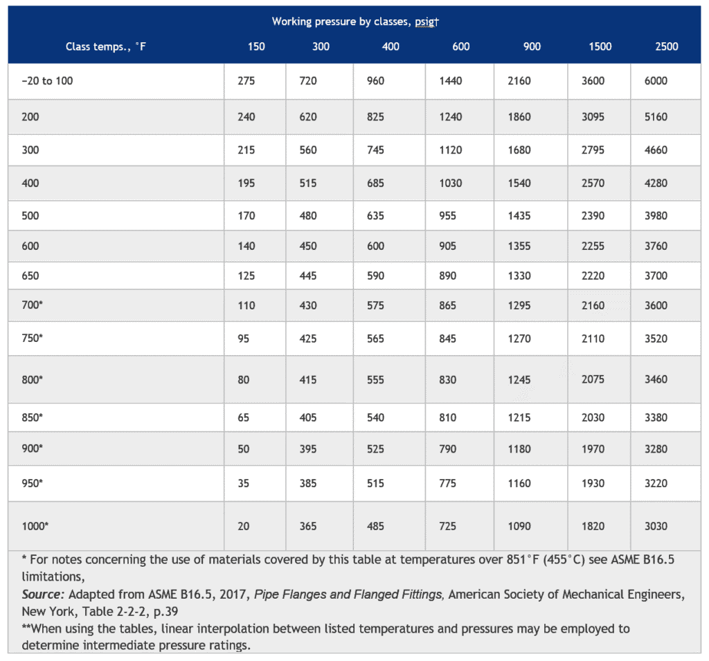
Table B2.1 is the adaption from ASME Standard B16.5 and is typical of the 34 flange rating tables that provide the pressure-temperature ratings for the flanges in the 2.1 material group.
The tables you will find below are organized as per the pressure classes that you can find at the top. At the left-hand border, you can also find the maximum working temperatures.
During the practice, using ASME B16.5 to determine the rating of the flange is relatively easy. Below is the recommended three-step process:
a. Determine the maximum temperature and operating pressure required for the flange.
b. You can select the material of the flange from the material groups of the 44 listed materials. Be aware of the qualifying notes that concern maximum operating temperatures for various materials that may influence the final material selection.
c. You must consult the right group table of material. You can start with the temperature listed in one increment higher than the desired maximum operating temperature.
Try to start with the Class 150 column and then proceed to the right until you find the proper pressure rating for the desired temperature, exceeding or equal to the required operating pressure.
The specified column that can satisfy the requirements can dictate the required pressure class and determine the actual pressure-temperature rating of the flange.
ASTM A182 is one of the chrome-based material specifications from material group 2.2.
If you consult Table B2.2 at a temperature of 650°F (343°C), a Class 600 flange has a rating of 890 psig (6136 kPa gage) at 650°F (343°C).
Table A1.1 Materials Used for ASME B16.5 Flange Construction (Partial Listing)
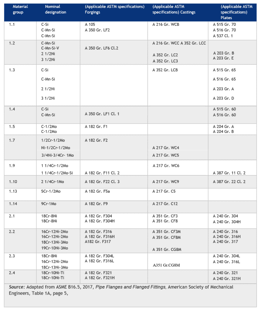
Table B1.1 Pressure-Temperature Ratings for ASME B16.5 Flanges Made from Material Group 1.1 Materials
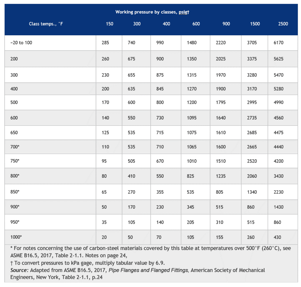
Table B2.1 Pressure-Temperature Ratings for ASME B16.5 Flanges Made from Material Group 2.1 Materials
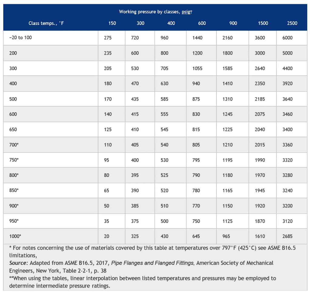
Table B2.2 Pressure-Temperature Ratings for ASME B16.5 Flanges Made from Material Group 2.2 Materials
If you still have questions about how to select flanges, let us know in the comment section or call us today!