Flange Bolt Torque Values: A Reference Guide for Every Pressure Class
You can have the right flange, the right gasket, and the right bolts, and still end up with a leak if the torque is wrong. Flange bolt torque is one of the most searched topics in piping for good reason: getting it right is the difference between a sealed joint and an unplanned shutdown. This guide covers the torque values you need for ASME B16.5 flanged connections, how those values are determined, and why a single torque chart will never tell the whole story.
Why Flange Bolt Torque Matters
When you tighten a flange bolt, you are not just making it “tight enough.” You are generating a specific clamping force (called bolt preload) that compresses the gasket between the flange faces. That gasket compression is what creates the seal. Too little torque and the gasket does not seat properly, which means it leaks under pressure. Too much torque and you risk crushing the gasket, yielding the bolt, or warping the flange face.
The target torque for any given joint depends on several variables: bolt diameter, bolt material grade, gasket type, gasket seating stress requirements, the number of bolts in the pattern, and whether the threads are lubricated or dry. ASME PCC-1 (Guidelines for Pressure Boundary Bolted Flange Joint Assembly) is the primary reference document that governs how to calculate and apply flange bolt torque values. If you work with flanged connections and have not read ASME PCC-1, it is worth your time.
How Target Torque Is Calculated
ASME PCC-1 Appendix K provides a simplified method for determining target bolt torque. The basic formula is:
T = K x D x F / N
Where T is the target torque per bolt, K is the nut factor (accounts for friction), D is the nominal bolt diameter, F is the total bolt load required, and N is the number of bolts.
The nut factor (K) is the variable that trips people up the most. For unlubricated carbon steel studs and nuts, K is typically around 0.20. With moly-based lubricant, it drops to approximately 0.13 to 0.15. With PTFE-coated studs, it can go as low as 0.10. That means the same target preload can require dramatically different torque values depending on lubrication. A joint that needs 200 ft-lbs with lubricated threads might need over 300 ft-lbs dry. This is why torque charts without specifying lubrication conditions are only half the picture.
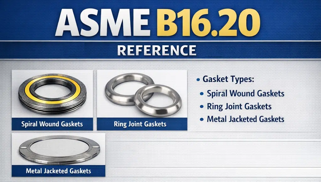
The total bolt load (F) is driven by the gasket’s required seating stress, the internal pressure of the system, and the hydrostatic end force acting on the flange. For standard ASME B16.5 flanges with spiral wound gaskets (ASME B16.20), the gasket seating stress is well documented and most torque references already factor it in.
Reference Torque Values for ASME B16.5 Flanges
The table below provides typical target torque values for ASME B16.5 flanged joints using SA-193 B7 studs, SA-194 2H heavy hex nuts, and standard spiral wound gaskets with graphite filler. These values assume lubricated threads (K = 0.13 to 0.15, moly-based or equivalent). For dry or unlubricated conditions, multiply by approximately 1.5. Confirm bolt count, diameter and stud length for your size and class before applying any figure below.
Flange Bolt Torque Reference Values
PTFE Coated Bolt reference guide:
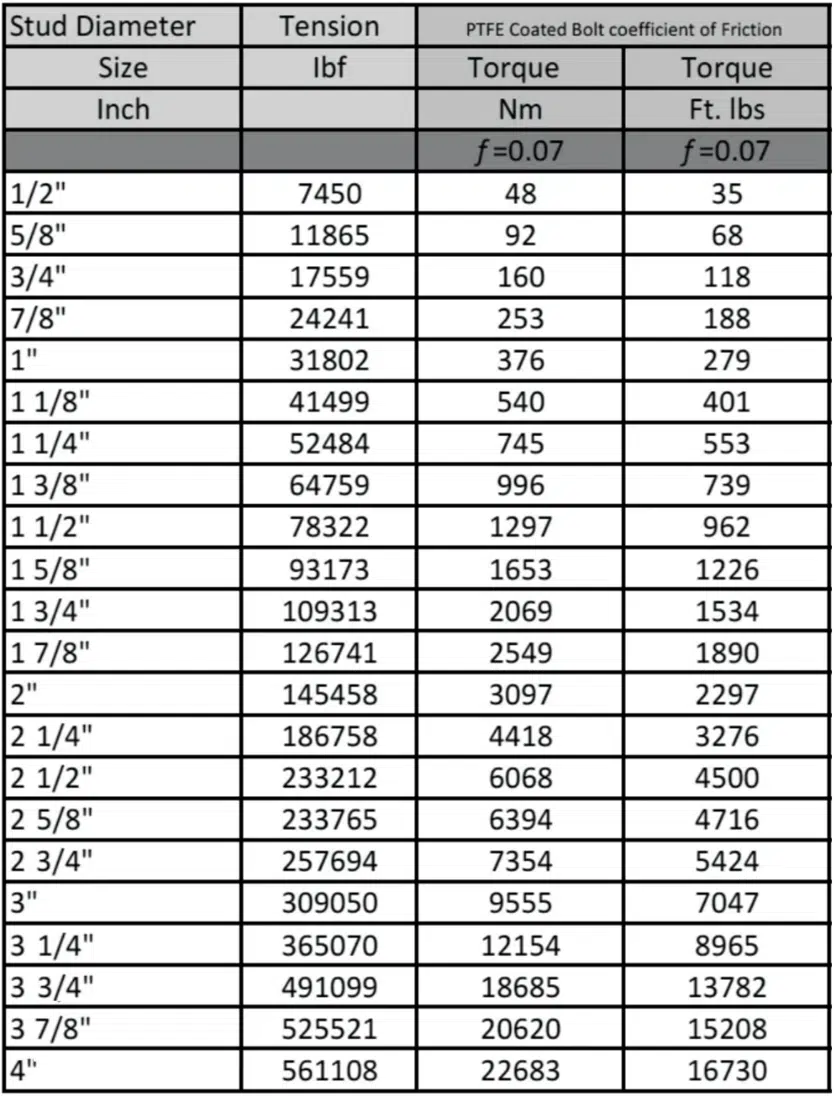
These are general reference values for initial guidance. Final torque should always be verified against the specific gasket manufacturer’s recommendations and the project’s engineering specifications. For ring type joint (RTJ) gaskets per ASME B16.20, seating stresses and therefore torque values will differ from spiral wound gaskets.
The Tightening Sequence: Star Pattern and Multi-Pass
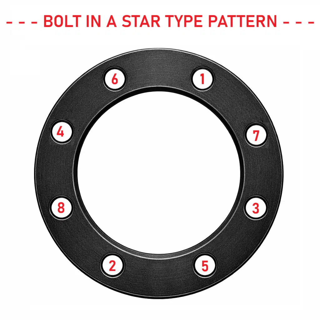
Getting the right torque value means nothing if you apply it incorrectly. ASME PCC-1 specifies a cross-pattern (star pattern) tightening sequence in multiple passes. For a standard ASME B16.5 flange with 8 or more bolts, the recommended approach is:
Pass 1: Tighten in star pattern to approximately 30% of target torque. Check flange alignment.
Pass 2: Star pattern to approximately 60% of target torque.
Pass 3: Star pattern to 100% of target torque.
Pass 4: Circular pattern (clockwise) at 100% of target torque until no further nut rotation occurs. This final circular pass addresses cross-talk, which is the loss of preload in previously tightened bolts caused by elastic interaction as adjacent bolts are tightened.
If you want a deeper walkthrough of the tightening procedure itself, including how to handle uneven gaps and troubleshooting, we have a step-by-step guide to tightening flange bolts that covers the process in more detail.
Common Mistakes That Lead to Leaks
Most flange leaks are not caused by defective flanges or gaskets. They are caused by assembly errors. The most common mistakes we see are: using no lubricant on studs (which makes the actual preload unpredictable even at the correct torque reading), skipping the multi-pass sequence and going straight to full torque in one pass, mixing bolt grades or using bolts with damaged threads, reusing old gaskets, and not verifying flange face condition before assembly.
One mistake that is often overlooked is using the wrong nut factor. If your torque table was calculated for lubricated threads and you install dry studs, you will under-load the gasket by 30% or more. That is enough to cause a leak at operating pressure even though the torque wrench read the “correct” number.
When to Go Beyond Standard Torque Tables
Standard torque charts work well for most ASME B16.5 applications with common gasket types. But certain conditions require additional engineering review: high-temperature service where bolt relaxation occurs over time (above 750 degrees F for B7 studs), cryogenic service where differential thermal contraction affects preload, large-diameter flanges (NPS 24 and above, or ASME B16.47), cyclic pressure or thermal cycling applications, and any joint where the consequences of failure are severe (toxic or flammable service per ASME B31.3 Category M). Dimensions for the higher classes are in our Class 900 flange dimensions and Class 1500 flange dimensions tables.
For these applications, ASME PCC-1 Appendix O provides a more rigorous calculation method that accounts for gasket relaxation, bolt elastic interaction, and flange rotation. Many critical facilities also specify hydraulic tensioning over torquing for joints 1″ and larger, which provides more accurate and uniform preload.
What Texas Flange Can Do
We carry flanges across every ASME B16.5 pressure class from 150# through 2500#, plus ASME B16.47 and API 6A, in carbon steel, stainless steel, alloy, and specialty materials. When you order flanges from us, we can confirm the bolt requirements for your specific size, class, and face type, and point you to the right torque data for your gasket selection. Need bolt dimension charts to go with your torque values? We have those too.
If you are specifying flanges for a project and need to confirm availability, lead times, or technical details, contact Texas Flange today. We will tell you what we have, what we can get, and how fast.
Texas Flange & Fitting Supply | 281-484-8325 | texasflange.com